Installation of any power or lighting network, repair of equipment and other electrical work is always associated with checking the integrity of circuits. Often, faulty wiring or a component is the result of broken patch lines, which can be diagnosed by using a wire gauge. This article will review the methods of the wiretap, and detail the option of diagnosing a circuit using a multimeter ..
Contents
What does it mean to make a wire gauge and when it may be necessary
You may hear the term "wire stripping" quite often, but it may not be understood by people who are not connected with electrical engineering. In a general sense, "wire tapping" means checking the integrity of electrical circuits and the absence of short circuits between conductors. Determining the integrity of conductors is carried out not only by electricians, but also by people involved in repair and diagnostics of various electrical equipment and electronics, as well as telecommunication workers when laying communication lines.
When installing power and lighting networks in industrial environments or households, at the end of all work (or any stages) make it mandatory to check each installed line. This is important for the correct and durable operation of the entire installed system.
What can be used to test the wires?
There are quite a number of options for diagnostic equipment to check the integrity of electrical circuits and detect short circuits. Such devices include:
- various testers: on the market are presented in a wide variety for electrical networks and communication lines from simple Chinese-made, to expensive from European manufacturers;
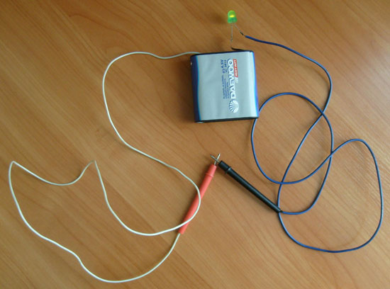
- home-made testers: based on an autonomous power supply (rechargeable battery) and a tester lamp;
- multimetersMultimeters: Multifunctional devices for measuring network characteristics and diagnosing network performance;
Professional electricians often use a multimeter when working on wire-clearing circuits, because this handy device is available in the arsenal of every specialist. In domestic conditions, for single checks and in the absence of a multimeter, testing conductors is carried out with homemade test lamps or by connecting a load.
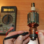
How to test wires with a multimeter
The most convenient, clear and safe way to diagnose wires for continuity or short circuit is to check with a multimeter. There are a large number of multimeter devices with different parameters and prices: from the simplest and most affordable, to more expensive, accurate and functional. But with almost any multimeter you can check the integrity of the conductors, it is not necessary to have expensive equipment.
What should be the reading of a multimeter
There are two methods of testing with such a device: in the resistance measurement mode and in the "continuity test" mode.
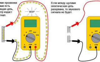
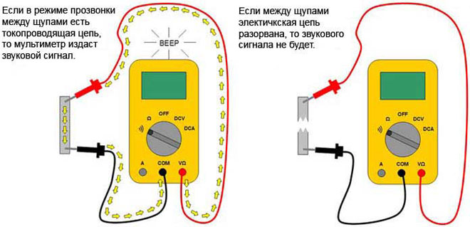
The continuity test mode - is the most convenient method of testing. Here you do not need to have any knowledge about the readings of the device. It is enough to connect the styli of the device to the cable ends and hear the sound. In order, the procedure is as follows:
- Turn on the multimeter, set the test mode (the icon of several brackets of different sizes, by analogy with the designation of Wi-Fi);
- Connect one probe to one end of the tested conductor, the other probe to the other end of the same wire;
- If you hear sound, then the cable is intact. If there is no sound - there is a break in the line (or the probes are connected incorrectly).
It should be noted that this way also checks the presence of a short circuit in adjacent conductors. The only difference is that one probe is connected to the first conductor, and the second probe to the second: if there is sound - there is a short circuit.
Resistance measurement mode - is a bit more complicated. But if you remember what readings should be on the multimeter in different situations, it will be much easier. Moreover, many multimeters do not have a continuity mode, but resistance measurement mode is almost always available.
The procedure for this measurement will be as follows:
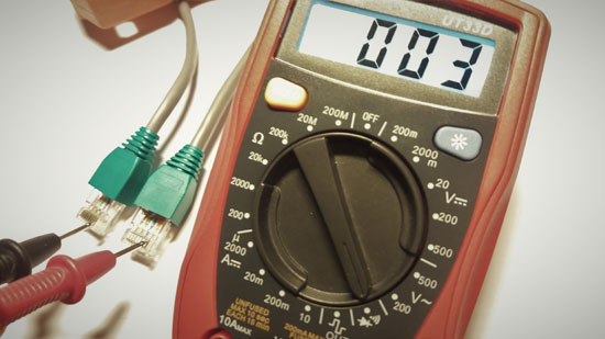
- Turn on the device, set the switch to resistance measurement mode, set the minimum value to measure (usually 200 Ohm);
- Connect the probe to the conductor;
- If there will be any value or zero on the display, the conductor is intact. If you see the number 1 on the screen - it means that the resistance is infinite, i.e. the cable is broken.
The reverse sequence to determine the short circuit between the conductors or ground: if the resistance is infinite - the insulation between the conductors is not broken, and the presence of any resistance will mean a short circuit.
Note! It is not always possible to determine a short circuit with a multimeter. To check the integrity of the insulation and the absence of inter-phase short circuits, check it with a megohmmeter ..
If you are sure of the integrity of the cable, you can use this method to identify the ends of the same conductor in a bundle of wires with the same color markings. It is enough to connect the probe to the conductor on one side, and on the other side touch the probe to each conductor in the bundle in turn. When the signal sounds, you have found the other end of the wire. That's it, nothing easier.
Wire Wire Feeding a Long Conductor
To test a wire whose ends are far away and there is no possibility to reach with two styli of the multimeter from the beginning to the end of the wire, you can use known wires or ground. For example, the cable may have a colored core, then all the white cores can be called by connecting it with the white ones at one end and looking for this pair at the other.
If there is no such a possibility, you can use grounding. Connect the wire strand to ground at one end, and look for the conductor sitting on ground at the other end. It is important to make sure that the grounding is reliable at both ends, otherwise you will not be able to test the wire in this way.
Safety rules when making a wire tap
Any electrical work, including the diagnosis of conductors requires compliance with all precautions and electrical safety rules. The main rules, the observance of which will save your life and health are as follows:
- Always work only when the power is off. Put up a sign. "DO NOT TURN ON. PEOPLE WORKING!" near a switch or circuit breaker;
- Do not touch exposed conductors with bare hands; use protective clothing and special tools;
- Use sharp-edged power tools with care: use gloves and do not damage the cable;
- When the work is finished, all defective systems must be de-energized, and the bare wires at the end of the work, all defective systems must be de-energized, and exposed wires - At the end of the work, all malfunctioning systems must be de-energized and all exposed wires must be properly insulated.
Take care of yourself and remember, if you doubt that you can work with electrical networks - entrust this business to professionals.
Related articles: