Transformer is an electromagnetic device used to convert alternating current of one voltage and frequency into alternating current of another (or equal) voltage and the same frequency.
Contents
Design and functioning of a transformer
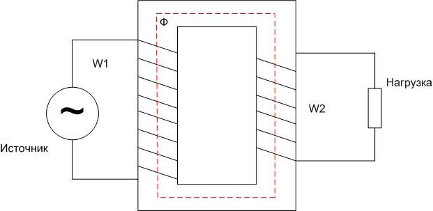
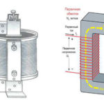
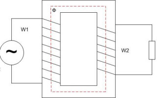
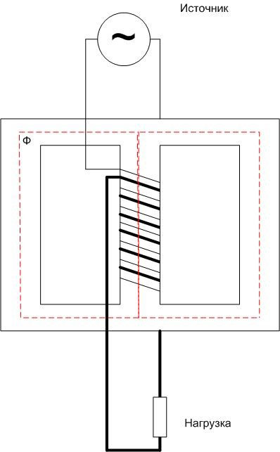
In its simplest form transformer has a primary winding with the number of windings W1 and a secondary with W2. Energy is supplied to the primary winding, the load is connected to the secondary winding. The energy is transferred by electromagnetic induction. To enhance the electromagnetic coupling, in most cases the windings are placed on a closed core (magnetic core).
If an alternating voltage U1then an alternating current I1which creates a magnetic flux F of the same shape in the core. This magnetic flux induces an EMF in the secondary winding. If a load is connected to the secondary circuit, a secondary current I2.
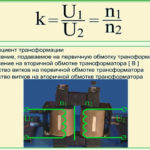
The voltage in the secondary winding is determined by the ratio of turns W1 and W2:
U2=U1*(W1/W2)=U1/k, where k transformation ratio.
If k<1 then U2>U1, and such a transformer is called a step-up transformer. If k>1 , then U2
A transformer can have more than one secondary winding with different ratios. For example, a 220 volt transformer for supplying household light bulbs can have one secondary winding, e.g. 500 volt to supply the anode circuits and 6 volt to supply the incandescent circuits. In the first case k<1, in the second case k>1.
Transformer works only with alternating voltage - for EMF to occur in the secondary winding, the magnetic flux must change.
Types of cores for transformers
In practice, cores of not only the specified shape are used. Depending on the purpose of the device, the magnetic cores can be made in different ways.
Core cores
Low-frequency transformer cores are made of steel with pronounced magnetic properties. To reduce eddy currents the core array is assembled from individual plates that are electrically insulated from each other. For operation at high frequencies, other materials such as ferrites are used.
The core discussed above is called a rod core and consists of two rods. For single-phase transformers, three-core cores are also used. They have less magnetic stray flux and higher efficiency. In this case, both the primary and secondary windings are placed on the central core.
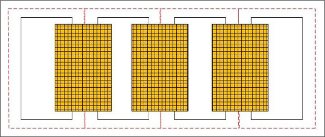
Three-phase transformers are also made on three-phase cores. The primary and secondary windings of each phase are each on its own core. In some cases, five-core cores are used. The windings are arranged in exactly the same way, the primary and secondary each on its own core, and the two outermost rods on each side are only used to short-circuit the magnetic fluxes in certain modes.
Armored
Single-phase transformers are made in an armored core - both coils are placed on the central core of the magnetic core. The magnetic flux in such a core is short-circuited similarly to the three-core design - through the side walls. The scattering flux in this case is very small.
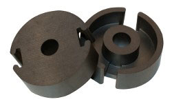
The advantages of this design include some gain in size and weight due to the possibility of denser filling of the core window by the winding, so it is advantageous to use armored cores for the manufacture of low-power transformers. A consequence of this is also a shorter magnetic circuit, which leads to lower no-load losses.
The disadvantages are more difficult access to the windings for inspection and repair, as well as increased difficulty in producing insulation for high voltages.
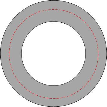
Toroidal
With toroidal cores, the magnetic flux is completely enclosed within the core, and there is virtually no magnetic flux dissipation. But these transformers are difficult to wind, so they are rarely used, e.g. in regulated autotransformers of low power or in high-frequency devices where interference immunity is important.
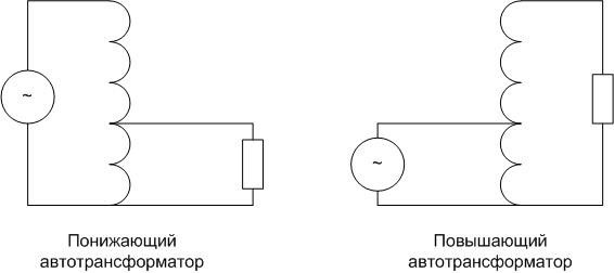
Autotransformer
In some cases it is advisable to use transformers in which there is not only a magnetic connection between the windings, but also an electrical one. That is, in a step-up device, the primary winding is part of the secondary winding, and in a step-down device, the secondary winding is part of the primary winding. Such a device is called an autotransformer (AT).
A step-down autotransformer is not a simple voltage divider - magnetic coupling is also involved in transferring energy to the secondary circuit.
The pros of autotransformers are:
- lower losses;
- the ability to smoothly regulate the voltage;
- less weight and dimensions (autotransformer is cheaper, it is easier to transport);
- lower cost due to the lower required amount of material.
The disadvantages include the need for insulation of both windings, designed for higher voltage, as well as the lack of galvanic isolation between input and output, which can transfer the effects of atmospheric phenomena from the primary circuit to the secondary circuit. At the same time, elements of the secondary circuit cannot be grounded. Also, increased short-circuit currents are considered a disadvantage of ATs. With three-phase autotransformers, the windings are usually connected in star with a grounded neutral, other connection schemes are possible, but too complicated and cumbersome. This is also a disadvantage that limits the use of autotransformers.
Transformer applications
The property of transformers to increase or decrease voltage is widely used in industry and in the home.
Voltage transformation
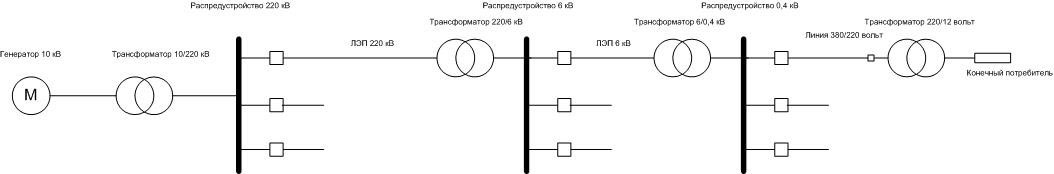
There are different requirements for the level of industrial voltage at different stages. For various reasons, it is not profitable to use high-voltage generators in the generation of electrical energy. That's why, for example, generators of 6...35 kV are used at hydroelectric power plants. On the contrary, higher voltages are needed for power transportation - from 110 kV to 1150 kV, depending on the distance. This voltage is then reduced again to 6...10 kV, distributed to local substations, from where it is reduced to 380(220) volts and comes to the end consumer. For household and industrial appliances, it must still be lowered, usually to 3...36 volts.
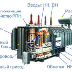
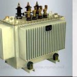
All these operations are carried out with the power transformers. They can be of dry or oil version. In the second case, the core with windings is placed in a tank with oil, which is an insulating and cooling medium.
Galvanic isolation
Galvanic isolation increases the safety of electrical devices. If you do not power the device directly from 220 volts, where one of the conductors is connected to ground, but through a 220/220 volt transformer, the supply voltage remains the same. But if the ground and the secondary current carrying parts touch at the same time, there will be no circuit for the current to flow and the risk of electrocution will be much lower.
Voltage Measurement
In all electrical installations, voltage levels must be monitored. If a voltage class up to 1000 volts is used, voltmeters are connected directly to the live parts. In installations above 1,000 volts this is not the case - devices that can withstand this voltage are too bulky and unsafe in case of an insulation breakdown. Therefore, in such systems, voltmeters are connected to high-voltage conductors through transformers with a convenient transformation ratio. For example, for 10 kV networks, 1:100 measuring transformers are used, the output is a standard voltage of 100 volts. If the primary voltage changes in amplitude, it also changes in the secondary at the same time. The scale of a voltmeter is usually graduated in the primary voltage range.
The transformer is a rather complicated and expensive component to manufacture and maintain. However, these devices are indispensable in many areas, and there is no alternative.
Related articles: