The color coding of conductor insulation is important for faster and correct installation of electrical distribution devices, ease of repair and avoidance of errors. The colors of wires in the electrical industry are regulated by regulatory documents (PUE and GOST R 50462-2009).
Content
Why wire and cable color coding is necessary
Installation and maintenance work in electrical installations is not only a matter of reliability, but also of safety. Errors must be ruled out completely. For this purpose, a core insulation color coding system has been developed that determines what color the phase, neutral and ground of a wire is.
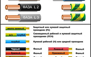
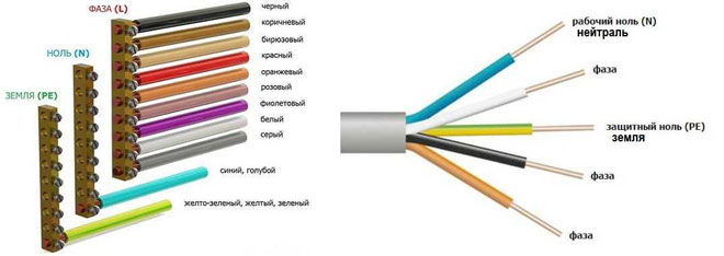
According to the PUE, the conductors can be color-coded as follows:
- red;
- brown;
- black; brown
- gray;
- white; brown; black; gray; white;
- pink;
- orange; orange;
- turquoise;
- purple.
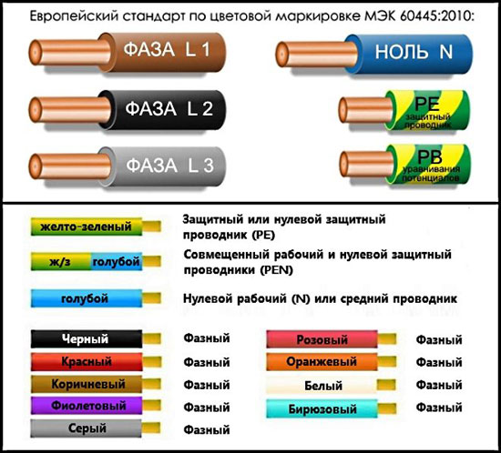
The list above contains many color options for wire colors, but there are a few colors that are only used to indicate neutral and protective conductors:
- blue and its shades - working neutral wire (neutral - N);
- yellow with a green stripe - protective earth (PE);
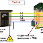
- yellow-green insulation with blue stripes at wire ends - combined (PEN) conductor.
Green insulated conductors with a yellow stripe may be used for grounding, and blue insulated conductors with yellow-green markings on the ends may be used for bonded conductors.
The coloring shall be the same on each circuit within a single unit. Branch circuits shall be made with identically colored conductors. The use of insulation with no differences in color indicates a high culture of installation and greatly facilitates future maintenance and repair of equipment.
Phase coloring
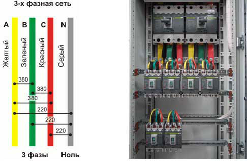
In cases where the installation of an electrical installation is carried out using rigid metal busbars, the busbars are painted with indelible paint in the following colors:
- yellow - phase A (L1);
- green - phase B (L2);
- red - phase C (L3);
- blue - zero bus;
- yellow and green longitudinal or slanting bars - ground bus.
The coloring of the phases must be maintained throughout the unit, but not necessarily on the entire bus surface. It is acceptable to mark the phase designation only at the connection points. On a painted surface, the color can be duplicated by the symbols "LZC"for the color of the paint in the corresponding colors.
If the busbars are not accessible for inspection or operation when voltage is present, it is permissible not to paint them.
The color of the phase conductors connected to rigid busbars may not match in color because of the difference in the accepted marking systems of flexible conductors and rigid fixed distribution busbars.
Neutral color
What color neutral wire is, the standards stipulate GOSTTherefore, when looking at the installation of a power system, the question should not arise whether the blue wire is the phase or zero, because the color blue and its shades (blue) is the color used to represent the neutral (work ground).
No other neutral colors are permitted.
The only permissible use of blue and blue insulation is to indicate the negative pole or midpoint in DC circuits. This color cannot be used anywhere else.
Color coding of the ground wire
Regulations specify what color the ground wire in electrical installations is. This is a yellow-green wire whose coloring stands out well against the rest of the wires. It is permissible to use a wire with yellow insulation and a green stripe on it, or it may be green insulation with a yellow stripe. No other color of ground wire is permitted, nor is it permitted to use green-yellow conductors for the installation of circuits on which voltage is present or may be present.
The above marking rules are observed in the countries of the former Soviet Union and the European Union. Other states mark cores in a different way, which can be seen on imported equipment.
The main colors for marking abroad are:
- neutral - White, gray or black;
- protective earthing - Yellow or green.
Standards in some countries allow bare metal without insulation to be used as a protective ground.
Grounding wires are switched on the prefabricated non-insulated terminals and connect all metal parts of the structure, which do not have a reliable electrical contact with each other.
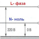
Coloring in the network 220V and 380V
Installation of single- and three-phase electrical networks is facilitated if the wiring is made with multi-colored wire. Previously, for single-phase apartment wiring, flat two-core wire in white. When installing and repairing to avoid errors it was necessary to test each core separately.
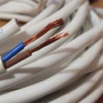
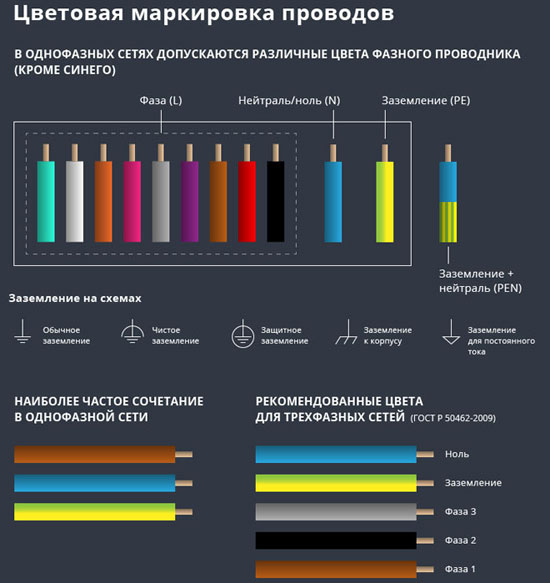
The production of cable products with different colors of cores reduces the labor intensity of the work. The following colors are commonly used to indicate the phase and zero in single-phase wiring:
- red, brown or black - phase wire;
- other colors (preferably blue) is the neutral wire.
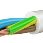
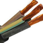
The marking of the phases in a three-phase network is slightly different:
- red (brown) - 1 phase;
- black - 2 phase;
- gray (white) - 3 phase;
- blue (blue) - operating zero (neutral)
- yellow-green - grounding.
Cable products of domestic production meet the standard of core coloring, so multiphase cable contains multi-colored cores, where the phase is white, red and blackzero - blue, and ground is yellow-green conductors.
When you service networks that are installed according to modern standards, you can unmistakably determine the assignment of the wires in the junction boxes. If there is a bundle of different-colored wires, the brown wire will necessarily be a phase wire. The neutral wire in junction boxes The neutral wire does not have any branches or gaps. Exceptions are branches to multipole switchgear with a full circuit break.
Coloring in DC networks
For DC circuits, it is common practice to mark conductors connected to the positive pole in red, and to the negative pole in black or blue. In bipolar circuits, blue insulation is used when marking the midpoint (zero...) of the power supply.
There are no standards for color coding on circuits with multiple voltage ratings. What color the plus and minus wires are, what voltage they carry, can only be determined by Deciphering of the manufacturer of the device, which is often found in the documentation or on one of the walls of the design.
Example: Computer power supply or automotive wiring.
Automotive wiring is characterized by the fact that in it the circuits with positive on-board voltage are red or its shades (pink, orange), and those connected to the ground are black. The other wires have a specific coloring, which is determined by the car manufacturer.
Letter designation of wires
Color marking can be supplemented with letter marking. Symbols for designation are partially standardized:
- L (from the word Line) is a phase wire;
- N (from the word Neutral) is the neutral wire;
- PE (from the combination Protective Earthing) - grounding;
- "+" is the positive pole;
- "-" is the negative pole;
- M - middle point in DC circuits with bipolar power supply.
To designate the connection terminals protective grounding a special symbol is used, which is stamped on the terminal or applied to the body of the device in the form of a sticker. The ground symbol is the same in most countries of the world, which reduces the likelihood of confusion.
In multi-phase networks, the symbols are complemented by the serial number of the phase:
- L1 - first phase;
- L2 - second phase;
- L3 - third phase.
An older standard designation may be encountered, where the phases are indicated by the symbols A, B, and C.
A departure from the standards is the combined phase designation system:
- La - first phase;
- Lb - second phase;
- Lc - third phase.
In complex devices there may be additional designations describing the name or number of the circuit. It is important that conductor designations match throughout the circuit in which they are involved.
Letter markings are applied in indelible, legible paint to the insulation near the ends of the conductors, to PVC insulation strips or heat shrink tubing.
Connection terminals may have applied symbols indicating circuits and polarities. These marks are made by paint, stamping or etching, depending on the material used.
Related articles: