Internet is tightly integrated into people's lives. Thanks to new technology, connecting to it has become easy and inexpensive. It is enough to have a desktop computer, laptop or smartphone.
Local distribution of Internet resources is done via a wired or wireless network. Despite the mobility of wireless connections, wired networks are still very common. They are chosen because of their high reliability, price and security.
It is desirable to carry out the distribution of Internet cables at the stage of renovation, while there is still an opportunity to hide the wires into the wall. At the same time in the areas where the wires exit, sockets with special RJ-45 connector are installed. Their connection to the wires is made by crimping the socket contacts with a special tool.
Contents
Options for using RJ-45 Internet outlets
Private households lead the way in the number of wired networks. However, sockets for Internet cables find their application in other areas as well.
The requirements for the technical characteristics of these devices vary depending on the type of room in which they will be installed. Conventionally, they can be divided as follows:
- office premises;
- internet clubs;
- server rooms;
- trading places;
- buildings and premises with increased protection against hacking.
No modern office building can do without access to the Internet or a local network. That means that the Internet socket is an essential attribute of such premises. In this case it can be not only mounted in a wall, but also attached to the workplace. The second method is preferable, since openly laid wires are much faster out of order and violate the aesthetic appearance of the room.
The existence of modern educational institutions is unthinkable without the presence of computer classes, online libraries and various multimedia devices. For this reason, the RJ45 socket in such places is as common as an electrical socket.
As for bank vaults, government and corporate security buildings, it is necessary to create wired networks in such places, because wireless ones cannot provide proper security.
Types and types of Internet outlets
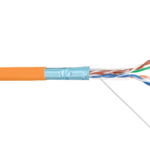
To implement a wired connection to the Internet, the RJ45 connector is used. This is a physical network standardized interface that contains a description of the design of the plug, the connector and the scheme of their connection to computing devices by means of an eight-wire wire.
Such a wire is called twisted pair. The reason for this is that it consists of four pairs of wires, intertwined with each other, and is designed to organize network connections. Twisted-pair insulation, depending on the application, is chosen with different thickness and properties.
RJ-45 Internet sockets are classified as follows:
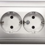
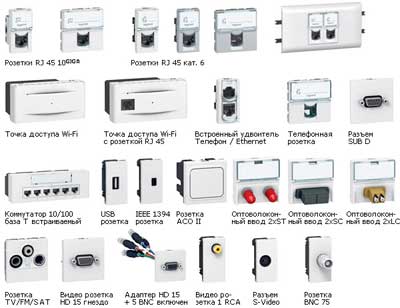
- By the number of connectors. There are single, double and terminal. The latter can contain from 4 to 8 outputs. There are also combined products, or keystones. Their layout also includes other connectors: USB, HDMI and power outlets. That is, the design provides for the division into 2 outputs, one of which gives access to the network, the other provides power to the device.
- Depending on the speed of data exchange. The division is done according to categories. The main are the following categories: 3 - communication speed up to 100 Mbit / s, 5 - provides data transfer speeds of up to 1 Gbit / s, 6 - up to 10 Gbit / s.
- According to the type of installation. As in the case of electrical outlets, fixtures come in internal and overhead. To install the indoor socket requires a technological recess and a protective plastic sub-socket in the wall under the contact group. The surface-mounted socket has a different mounting method. It is mounted to a pre-fixed mounting bar.
The cable for the overhead socket is preferably hidden under the plinth or in a separate cable-channel. This will protect it from negative environmental influences and prolong its service life.
Features of RJ 45 cable pinout
Connecting the RJ-45 outlet should not cause inconvenience. To make the task easier, each socket has a color pinout that conforms to T568A or T568B standards. This information can be marked with letters corresponding to standard A or B.
It does not matter which standard is used in this case, as long as all local network connections are made according to the same standard. The T568B standard is more common, but this is not always the case.
In order to determine which standard the ISP uses, you need to find out what pinout is on the cable coming into the room.
Another feature is the use of direct and crossover pinning, depending on the type of devices to be connected.
Direct is used to set up the connection between the consumer devices and the router. Cross-connection connects devices with similar functionality (PC-PC, router-router).
Connecting the RJ-45
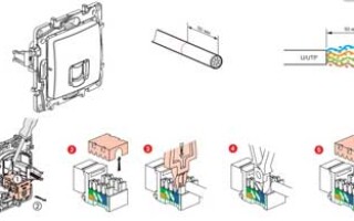
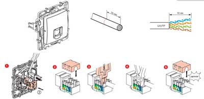
Twisted pair is hidden in the cable-channel or under the plinth. The end of the wire (in the case of flush mounting) is led through the socket out or just left uncovered. 6-7 cm from the edge. The outer insulation must be removed from this area. The pairs of wires are untwisted and align each wire.
In the case that the connector will be connected to the router, it is necessary to place a network socket nearby.
The sequence of how to connect the Internet cable to the socket looks like this:
- Disconnect the cover of the outlet. Under it there is a connection diagram for two standards: A and B. How to connect the cable depends on which standard the provider uses. You can check this information with him or use the method described above.
- After identifying the circuit, you should connect the twisted-pair wires. Directing the wires into the appropriate terminals, make sure that the color of the wires and the contacts of the microknots match. When installing the Rj 45 socket the wire ends are not stripped, they are pressed into the terminal until they click into place with the plastic extractor supplied. The click signals that the sheath has been cut, which means that the wires have been pressed and crimped, crimp the wires further if the extractor is not included in the kit and the necessary tool is not at hand.
- Fix the twisted pair on the body so that the stripped part was 3-5 mm above the clamp. After that we check the functionality of the connection of the socket Rj 45. We do it with a special tester or by connecting a computer. If the connection does not work, you should first check the pinout.
- Remove the excess wires and reassemble the socket.
- If the socket is overhead, mount it to the wall with the connector facing down, as installing it any other way will later damage the cable.
If shielded cable is used, it is necessary to connect the Internet socket with the possibility of installing a screen. Failure to do so will cause the shielding to fail and will adversely affect the transmission of information.
When implementing a twisted-pair LAN, twisting and splicing should be avoided. Solid wire is required. Locations of such connections cancel out the signal. If you need to increase the length of the cable, you should use a connector in which the signal from one cable to the other goes on special tracks.
Such a device consists of a board with Rj 45 connectors or terminals, as in the installation of Internet outlets.
When connecting to an outlet with internet access, twisted pair is also used, but only 4 of the 8 wires are involved.
The first pair is needed to receive data packets, the second pair is used to transmit them. In the case of a damaged wire, one of the free pairs is used or, using the remaining two pairs of wires, a second computer is connected.
Only the orange and green lines are used to connect the computer-hub network. The contacts are crimped to terminals of the same color on both ends.
Checking the wiring signals
Once the socket is plugged in, you should check that the signal is present and correct. The test is carried out with a household tester. This requires a patch cord with a straight pinout pattern and a length of 0.5 - 5 m.
Connect the other end of the laid wire to the test socket. Put the tester in the beep position and check the patch cord and socket channels. A beep signals the presence of the connection.
If the tester is not equipped with a buzzer device, you need to put it in resistance mode. The presence of the signal will be indicated by a change in the numbers on the screen.
A special cable tester also checks the signal. To do this you will need another patch cord with a direct circuit connection. To test the signal, plug one end of each cable into the jacks of the sockets. Plug the remaining ends into the tester. The signal from the cable tester will tell you if the connection is correct.
If there is no signal (and the connection was made by yourself, and the device to be connected was purchased with an assembled patch cord), it is necessary to check which circuit is used to assemble the patch cord and whether this circuit corresponds to the way the connector was connected.
The signal may be missing and if you bought a cheap socket, with poor quality soldering. It should be replaced by a better quality. This will save installation time and eliminate the possibility of breakage during the lifetime of the socket.
Related articles: